
 A top end rebuild on a two stroke dirt bike is a basic and routine part of maintaining the health and performance of your machine. The frequency and complexity of each rebuild will vary depending on many factors, some of which include the type of riding you do, the age of the bike(and/or hours on the motor), quality of parts used, tools available and so on.
 First
Wash your bike thoroughly with soap and water. Even if your bike looks clean there could be mud or other debris stuck under the frame or in the nooks of the engine. I like to take my gas tank and seat off, plug the line to the carb and air box if you can and wash focusing on the underside of the frame and other areas where dirt could hide and fall into the motor during the project.
 |
| Checking The Compression |
Next
As I said before, a compression test is a good check and a base line measurement will help determine service intervals. Keep a log and you will be able to look back and see trends. With the compression tester threaded into the head, get on the bike and kick it hard about ten times with the throttle open. The pressure will build as you kick and the highest reading is the one you are interested in. Try to be consistent in how you measure to get a proper perspective. Kicking harder leads to higher readings to be consistent there as well. My initial reading before rebuild was about 170psi. Since I hadn't done checks before I didn't know if this was bad or good for my bike, but it was in the area I expected and still considered healthy. Higher elevations will produce a lower compression than the same motor at lower elevations. From my calculations you will lose about 3.3% for each 1000 feet rise in elevation, so a motor that produces 180 psi at sea level will drop to about 156 psi at 4,000 feet. If you ride higher elevations frequently and don't plan on dropping much, you may consider some head modifications to increase compression. A higher compression will help bottom to mid power, but you have to know where to stop and if it will have a bad effect on top end power, reliability, and fuel requirements. I did a head swap to boost the compression and was pleased with the results and the 170 reading. I'd like to be more around 180 to 190 however. This would still be safe for my bike while not affecting top end and not requiring special fuel. Fresh rings will help as would shaving the head(more on this later).
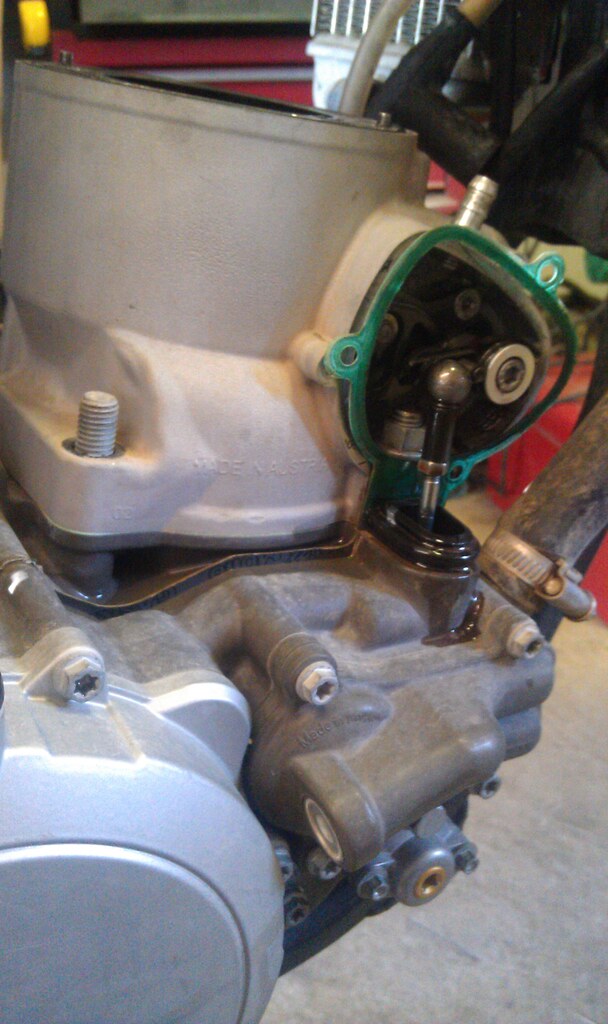 |
| Power Valve Linkage |
 |
| Rag Stuffed in Opening |
With the cylinder removed, wash it with soap and water. Every time you have the top end apart it's a good time to clean the power valve. Oven cleaner works well to remove grime and deposits. Power valves vary greatly between makes and models so have a manual handy and/or take note of how everything goes back together and how it works so you have a good understanding of how to put it back together. Replace any o-rings or seals that you remove in the process and oil the moving parts with two stroke oil as you re-assemble. Make sure everything works smooth and is working properly. Check for wear and play. A manual will have the tolerances. How far you go on the cleaning is really up to you. Any gunk you get off will help. I cleaned it once thinking I was done, then decided to fully disassemble the power valve to replace some o-rings and get more gunk out. I had the o-rings in my kit and decided it was worth the extra time and effort. Use scotch brite on the cylinder to remove glaze working in the direction of the hone marks. Make sure all the old gaskets are removed and never re-use an old gasket.
 |
| Power Valve, Initial Cleaning |
 |
| Measuring Bore |
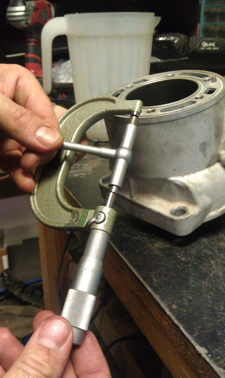 |
| Measuring Bore |
Measuring ring end gap is next. The gap should be .004" per 1.000" of bore. My cylinder has a 2.535"(66.4mm) cylinder bore, 2.535 x .004 =.010. My ring end gap should be no smaller than .010". To measure ring end gap gently push the ring into the cylinder bore so it is parallel and about 1/2" to 1" below the head surface. Use a feeler gauge to measure the end gap. Larger is OK, smaller has to be corrected because it won't allow for expansion when it heats. Use a flat file to remove material from the ends of the ring if needed. Normally, the maximum gap is 0.018–0.025 inch(gap should be between .012 and .024 inches). My old rings measured .031 and my new ones were .019, looks like it was a good time to replace them and the new rings didn't need to be altered.
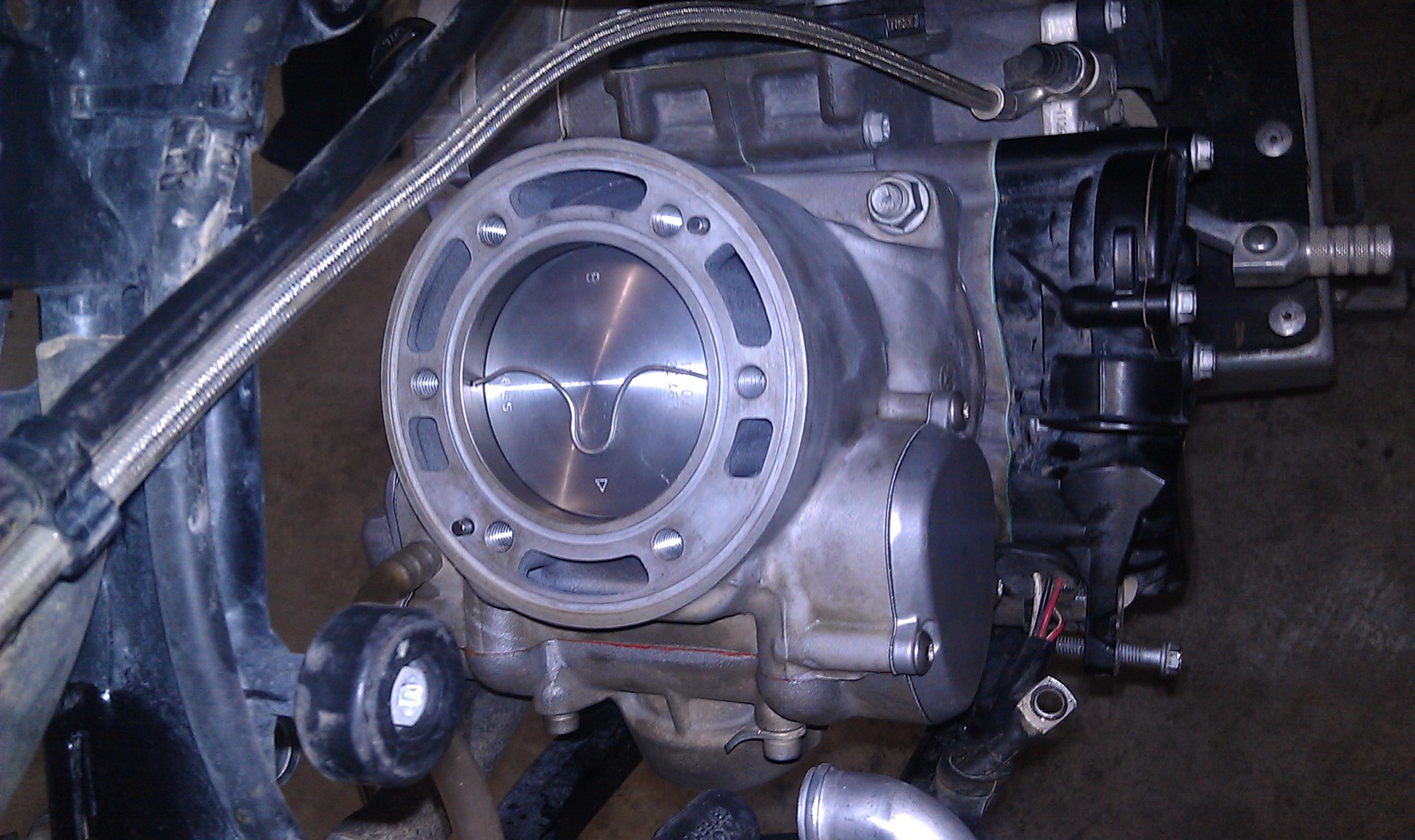
Now on to the assembly. Put the first wrist pin clip into the pin bore. Make sure that the clip is seated in the groove and the openings of the clip are facing up or down. Use a new wrist pin bearing and oil it before installing in the rod. Oil the wrist pin with 2-stroke oil as well. With the new wrist pin bearing in the rod and the arrow on the piston pointing toward the exhaust, slide the pin into the side of the piston without the clip and push through the rod and bearing. Now install the last clip into the piston bore. Install the rings on the piston with the marks on the rings facing up and lined up with the pins in the back of the piston. The arrow on the piston faces forward and the pins are in the back. Lightly oil the piston skirt with 2-stroke oil. Install the new base gasket, then squeeze the rings together with your fingers and gently lower the cylinder over the piston. It will go easily if you've measured the gap and they are lined up with the pins. Don't force it. Install the cylinder nuts and torque to spec. Make sure any power valve linkage is attached correctly.
 |
| Checking Squish |
Once everything is together and you've done a proper break in, check the compression again to see what improvements were made and to get another baseline. After break in my compression measured 180psi. Good enough, time to ride!
It’s actually a great and useful piece of info. I am satisfied that you shared this helpful info with us. Please keep us up to date like this. Thank you for sharing.
ReplyDeleteatv performance parts
God why do people still stick rags in their cases? Even if it is a clean rag lint or fuzz can come loose. Use a perfectly clean plastic shopping bag or a new plastic bag for waste baskets.
ReplyDeletewhat if the cyl wall is scarred
ReplyDeletePlaces like powersealusa can repair cylinders.
ReplyDelete